
ITU G.992.1
Encyclopedia
In telecommunications, ITU G.992.1 (better known as G.DMT) is an ITU
standard for ADSL
using discrete multitone modulation. G.DMT full-rate ADSL expands the usable bandwidth of existing copper telephone lines, delivering high-speed data communications at rates up to 8 Mbit/s downstream and 1.3 Mbit/s upstream.
DMT allocates from 2 to 15 bits per channel (bin). As line conditions change, bit swapping allows the modem to swap bits around different channels, without retraining, as each channel becomes more or less capable. If bit swapping is disabled then this does not happen and the modem needs to retrain in order to adapt to changing line conditions.
There are 2 competing standards for DMT ADSL - ANSI & G.DMT; ANSI T1.413 is a North American standard, G.992.1 (G.DMT) is an ITU (United Nations Telecom committee) standard. G.DMT is used most commonly today, throughout the world, but the ANSI standard was formerly popular in North America. There is a difference in framing between the two, and selecting the wrong standard can cause frame alignment errors every 5 or so minutes. Error correction is done using Reed-Solomon encoding and further protection can be used if Trellis
encoding is used at both ends. Interleaving
can also increase the robustness of the line but increases latency.
 Modulation is the overlaying of information (or the signal) onto an electronic or optical carrier waveform. There are two competing and incompatible standards for modulating the ADSL signal, known as discrete multitone modulation (DMT) and Carrierless Amplitude Phase
(CAP). CAP was the original technology used for DSL deployments, but the most widely used method now is DMT.
The graphs on the right summarise the speeds obtainable for each ADSL standard based on line length and attenuation. The second graph is of more importance since it is attenuation
which is the governing factor for line speed because attenuation rate over distance can vary significantly between various copper lines due to their quality and other factors. The second graph clearly shows that for longer lines exceeding around 50 dB attenuation, ADSL2
and ADSL2+
bring no benefit in terms of speed. However, ADSL2
is able to extend the reach of extremely long lines that have around 90 dB attenuation. Standard ADSL is only able to provide a service on lines with an attenuation no greater than about 75 dB.
) is used on the same line, then bin 7 is the lowest bin used for ADSL.
The centre frequency of bin N is (N x 4.3125) kHz. The spectrum of each bin overlaps that of its neighbours: it is not confined to a 4.3125 kHz wide channel. The orthogonality of COFDM makes this possible without interference.
Up to 15 bits per symbol can be encoded on each bin on a good quality line.
The frequency layout can be summarised as:
Typically, a few bins around 31-32 are not used in order to prevent interference between upstream and downstream bins either side of 138 kHz. These unused bins constitute a guard band to be chosen by each DSLAM manufacturer - it is not defined by the G.992.1 specification.
Using DMT is useful since it allows the communications equipment (user modem/router and exchange/DSLAM) to select only bins which are usable on the line thus effectively obtaining the best overall bit rate from the line at any given moment in time. With COFDM, a combined signal containing many frequencies (for each bin) is transmitted down the line. Fast Fourier Transform (and the inverse iFFT) is used to convert the signal on the line into the individual bins.
(QAM) or phase-shift keying
(PSK) is used to encode the bits within each bin. This is a complex and mathematical subject and will not be discussed further here. However, much research has been done on these modulation techniques and they are used for transmission because they allow the SNR to be improved, thus lowering the noise floor and enabling more reliable transmission of a signal with fewer errors. The gain obtainable above the noise floor can be anything from 0.5-1.5 dB and these small amounts make a vast difference when sending signals over long distance copper lines of 6 km or more.
s, it depends on the attenuation
and signal-to-noise ratio
.
SNR may differ for each bin and this plays an important factor for deciding how many bits can be encoded reliably on it. Generally speaking, 1 bit can be encoded reliably for each 3 dB of available dynamic range above the noise floor within a transmission medium so, for example, a bin with an SNR of 18 dB would be able to accommodate 6 bits.
Bin SNR Gain Bi - Bin SNR Gain Bi - Bin SNR Gain Bi - Bin SNR Gain Bi
dB dB ts dB dB ts dB dB ts dB dB ts
--- ----- ---- -- - --- ----- ---- -- - --- ----- ---- -- - --- ----- ---- --
0 0.0 0.0 0 * 1 0.0 0.0 0 * 2 0.0 0.0 0 * 3 0.0 0.0 0 <- unused
4 0.0 0.0 0 * 5 0.0 0.0 0 * 6 0.0 0.7 0 * 7 0.0 0.7 0 <- unused
8 0.0 0.9 2 * 9 0.0 1.2 4 * 10 0.0 1.0 5 * 11 0.0 0.8 5 <- upstream [BEGIN]
12 0.0 1.0 6 * 13 0.0 0.9 6 * 14 0.0 0.9 6 * 15 0.0 1.1 7 <- upstream
16 0.0 1.1 7 * 17 0.0 1.0 7 * 18 0.0 0.9 7 * 19 0.0 0.7 7 <- upstream
20 0.0 1.0 6 * 21 0.0 0.9 5 * 22 0.0 0.9 4 * 23 0.0 1.2 4 <- upstream
24 0.0 1.3 3 * 25 0.0 1.0 2 * 26 0.0 0.7 0 * 27 0.0 0.7 0 <- upstream [END]
28 0.0 0.7 0 * 29 0.0 0.0 0 * 30 0.0 0.0 0 * 31 39.9 0.9 6 <- downstream [BEGIN]
32 38.4 0.9 6 * 33 39.9 1.1 7 * 34 256.0 1.0 0 * 35 39.8 1.2 7 <- downstream (1 unused bin - interference?)
36 39.8 1.1 7 * 37 35.3 1.1 6 * 38 39.5 0.9 6 * 39 37.5 1.0 6 <- downstream
40 36.4 0.8 5 * 41 37.5 0.9 5 * 42 32.3 1.0 4 * 43 34.8 1.1 5 <- downstream
44 31.6 1.0 4 * 45 37.7 0.9 5 * 46 35.7 1.1 6 * 47 34.3 1.2 5 <- downstream
48 37.8 1.1 6 * 49 36.9 0.9 5 * 50 36.1 1.0 5 * 51 34.5 1.2 5 <- downstream
52 32.3 1.0 4 * 53 31.6 1.0 4 * 54 33.6 0.9 4 * 55 31.6 1.1 4 <- downstream
56 34.3 1.1 5 * 57 31.9 0.9 4 * 58 33.7 0.9 4 * 59 31.5 1.2 4 <- downstream
60 30.6 1.1 5 * 61 30.2 1.1 4 * 62 17.3 1.1 3 * 63 25.7 1.1 3 <- downstream
64 21.9 0.8 2 * 65 22.8 0.8 2 * 66 256.0 1.0 0 * 67 255.9 1.0 0 <- downstream (2 unused bins - interference?)
68 255.9 1.0 0 * 69 19.5 1.1 3 * 70 25.8 0.9 3 * 71 23.1 1.0 3 <- downstream (1 unused bin - interference?)
72 23.3 1.0 3 * 73 16.9 1.2 4 * 74 21.7 0.8 2 * 75 23.2 0.7 2 <- downstream
76 22.0 1.0 3 * 77 25.3 0.7 2 * 78 24.7 0.7 2 * 79 20.8 0.9 2 <- downstream
80 19.1 1.0 2 * 81 255.9 1.0 0 * 82 256.0 1.0 0 * 83 255.9 1.0 0 <- downstream [END]
84 0.1 1.0 0 * 85 255.8 1.0 0 * 86 255.8 1.0 0 * 87 255.9 1.0 0 <- unused
88 256.0 1.0 0 * 89 256.0 1.0 0 * 90 255.9 1.0 0 * 91 255.9 1.0 0 <- unused
92 256.0 1.0 0 * 93 255.9 1.0 0 * 94 255.8 1.0 0 * 95 255.3 1.0 0
96 0.1 1.0 0 * 97 255.6 1.0 0 * 98 255.8 1.0 0 * 99 255.9 1.0 0 higher frequencies suffer greater
100 255.9 1.0 0 * 101 255.8 1.0 0 * 102 255.8 1.0 0 * 103 0.0 1.0 0 loss rates over longer lines
104 255.8 1.0 0 * 105 255.7 1.0 0 * 106 255.2 1.0 0 * 107 255.6 1.0 0
108 255.6 1.0 0 * 109 254.6 1.0 0 * 110 255.9 1.0 0 * 111 254.6 1.0 0
112 254.7 1.0 0 * 113 255.4 1.0 0 * 114 254.7 1.0 0 * 115 255.2 1.0 0
116 256.0 1.0 0 * 117 256.0 1.0 0 * 118 256.0 1.0 0 * 119 256.0 1.0 0
120 256.0 1.0 0 * 121 256.0 1.0 0 * 122 256.0 1.0 0 * 123 256.0 1.0 0
124 256.0 1.0 0 * 125 256.0 1.0 0 * 126 256.0 1.0 0 * 127 256.0 1.0 0
128 256.0 1.0 0 * 129 256.0 1.0 0 * 130 256.0 1.0 0 * 131 256.0 1.0 0
132 256.0 1.0 0 * 133 256.0 1.0 0 * 134 256.0 1.0 0 * 135 256.0 1.0 0
136 256.0 1.0 0 * 137 256.0 1.0 0 * 138 256.0 1.0 0 * 139 256.0 1.0 0
140 256.0 1.0 0 * 141 256.0 1.0 0 * 142 256.0 1.0 0 * 143 256.0 1.0 0
144 256.0 1.0 0 * 145 256.0 1.0 0 * 146 256.0 1.0 0 * 147 256.0 1.0 0
148 256.0 1.0 0 * 149 256.0 1.0 0 * 150 256.0 1.0 0 * 151 256.0 1.0 0
152 256.0 1.0 0 * 153 256.0 1.0 0 * 154 256.0 1.0 0 * 155 256.0 1.0 0
156 256.0 1.0 0 * 157 256.0 1.0 0 * 158 256.0 1.0 0 * 159 256.0 1.0 0
160 256.0 1.0 0 * 161 256.0 1.0 0 * 162 256.0 1.0 0 * 163 256.0 1.0 0
164 256.0 1.0 0 * 165 256.0 1.0 0 * 166 256.0 1.0 0 * 167 256.0 1.0 0
168 256.0 1.0 0 * 169 256.0 1.0 0 * 170 256.0 1.0 0 * 171 256.0 1.0 0
172 256.0 1.0 0 * 173 256.0 1.0 0 * 174 256.0 1.0 0 * 175 256.0 1.0 0
176 256.0 1.0 0 * 177 256.0 1.0 0 * 178 256.0 1.0 0 * 179 256.0 1.0 0
180 256.0 1.0 0 * 181 256.0 1.0 0 * 182 256.0 1.0 0 * 183 256.0 1.0 0
184 256.0 1.0 0 * 185 256.0 1.0 0 * 186 256.0 1.0 0 * 187 256.0 1.0 0
188 256.0 1.0 0 * 189 256.0 1.0 0 * 190 256.0 1.0 0 * 191 256.0 1.0 0
192 256.0 1.0 0 * 193 256.0 1.0 0 * 194 256.0 1.0 0 * 195 256.0 1.0 0
196 256.0 1.0 0 * 197 256.0 1.0 0 * 198 256.0 1.0 0 * 199 256.0 1.0 0
200 256.0 1.0 0 * 201 256.0 1.0 0 * 202 256.0 1.0 0 * 203 256.0 1.0 0
204 256.0 1.0 0 * 205 256.0 1.0 0 * 206 256.0 1.0 0 * 207 256.0 1.0 0
208 256.0 1.0 0 * 209 256.0 1.0 0 * 210 256.0 1.0 0 * 211 256.0 1.0 0
212 256.0 1.0 0 * 213 256.0 1.0 0 * 214 256.0 1.0 0 * 215 256.0 1.0 0
216 256.0 1.0 0 * 217 256.0 1.0 0 * 218 256.0 1.0 0 * 219 256.0 1.0 0
220 256.0 1.0 0 * 221 256.0 1.0 0 * 222 256.0 1.0 0 * 223 256.0 1.0 0
224 256.0 1.0 0 * 225 256.0 1.0 0 * 226 256.0 1.0 0 * 227 256.0 1.0 0
228 256.0 1.0 0 * 229 256.0 1.0 0 * 230 256.0 1.0 0 * 231 256.0 1.0 0
232 256.0 1.0 0 * 233 256.0 1.0 0 * 234 256.0 1.0 0 * 235 256.0 1.0 0
236 256.0 1.0 0 * 237 256.0 1.0 0 * 238 256.0 1.0 0 * 239 256.0 1.0 0
240 256.0 1.0 0 * 241 256.0 1.0 0 * 242 256.0 1.0 0 * 243 256.0 1.0 0
244 256.0 1.0 0 * 245 256.0 1.0 0 * 246 256.0 1.0 0 * 247 256.0 1.0 0
248 256.0 1.0 0 * 249 256.0 1.0 0 * 250 256.0 1.0 0 * 251 256.0 1.0 0
252 256.0 1.0 0 * 253 256.0 1.0 0 * 254 256.0 1.0 0 * 255 256.0 1.0 0
--- ----- ---- -- - --- ----- ---- -- - --- ----- ---- -- - --- ----- ---- --
Bin SNR Gain Bi - Bin SNR Gain Bi - Bin SNR Gain Bi - Bin SNR Gain Bi
dB dB ts dB dB ts dB dB ts dB dB ts
International Telecommunication Union
The International Telecommunication Union is the specialized agency of the United Nations which is responsible for information and communication technologies...
standard for ADSL
Asymmetric Digital Subscriber Line
Asymmetric digital subscriber line is a type of digital subscriber line technology, a data communications technology that enables faster data transmission over copper telephone lines than a conventional voiceband modem can provide. It does this by utilizing frequencies that are not used by a voice...
using discrete multitone modulation. G.DMT full-rate ADSL expands the usable bandwidth of existing copper telephone lines, delivering high-speed data communications at rates up to 8 Mbit/s downstream and 1.3 Mbit/s upstream.
DMT allocates from 2 to 15 bits per channel (bin). As line conditions change, bit swapping allows the modem to swap bits around different channels, without retraining, as each channel becomes more or less capable. If bit swapping is disabled then this does not happen and the modem needs to retrain in order to adapt to changing line conditions.
There are 2 competing standards for DMT ADSL - ANSI & G.DMT; ANSI T1.413 is a North American standard, G.992.1 (G.DMT) is an ITU (United Nations Telecom committee) standard. G.DMT is used most commonly today, throughout the world, but the ANSI standard was formerly popular in North America. There is a difference in framing between the two, and selecting the wrong standard can cause frame alignment errors every 5 or so minutes. Error correction is done using Reed-Solomon encoding and further protection can be used if Trellis
Trellis modulation
In telecommunication, trellis modulation is a modulation scheme which allows highly efficient transmission of information over band-limited channels such as telephone lines...
encoding is used at both ends. Interleaving
Interleaving
In computer science and telecommunication, interleaving is a way to arrange data in a non-contiguous way to increase performance.It is typically used:* In error-correction coding, particularly within data transmission, disk storage, and computer memory....
can also increase the robustness of the line but increases latency.
DMT history and line rates
Carrierless Amplitude Phase Modulation
Carrierless amplitude phase modulation is a variant of quadrature amplitude modulation . Instead of modulating the amplitude of two carrier waves, CAP generates QAM signal by combining two PAM signals filtered through two filters designed so that their impulse responses form a Hilbert pair.CAP...
(CAP). CAP was the original technology used for DSL deployments, but the most widely used method now is DMT.
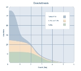
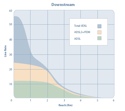
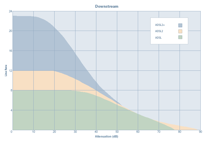
The graphs on the right summarise the speeds obtainable for each ADSL standard based on line length and attenuation. The second graph is of more importance since it is attenuation
Attenuation
In physics, attenuation is the gradual loss in intensity of any kind of flux through a medium. For instance, sunlight is attenuated by dark glasses, X-rays are attenuated by lead, and light and sound are attenuated by water.In electrical engineering and telecommunications, attenuation affects the...
which is the governing factor for line speed because attenuation rate over distance can vary significantly between various copper lines due to their quality and other factors. The second graph clearly shows that for longer lines exceeding around 50 dB attenuation, ADSL2
ITU G.992.3/4
ITU G.992.3 is an ITU standard, also referred to as ADSL2 or G.DMT.bis. It optionally extends the capability of basic ADSL in data rates to 12 Mbit/s downstream and, depending on Annex version, up to 3.5 Mbit/s upstream...
and ADSL2+
ITU G.992.5
ITU G.992.5 is an ITU standard, also referred to as ADSL2+ or ADSL2Plus. Commercially it is notable for its maximum theoretical download speed of 24 Mbit/s.-Technical information:...
bring no benefit in terms of speed. However, ADSL2
ITU G.992.3/4
ITU G.992.3 is an ITU standard, also referred to as ADSL2 or G.DMT.bis. It optionally extends the capability of basic ADSL in data rates to 12 Mbit/s downstream and, depending on Annex version, up to 3.5 Mbit/s upstream...
is able to extend the reach of extremely long lines that have around 90 dB attenuation. Standard ADSL is only able to provide a service on lines with an attenuation no greater than about 75 dB.
Bins (carrier channels)
Discrete Multi-Tone (DMT), the most widely used modulation method, separates the ADSL signal into 255 carriers (bins) centred on multiples of 4.3125 kHz. DMT has 224 downstream frequency bins and up to 31 upstream bins. Bin 0 is at DC and is not used. When voice (POTSPlain old telephone service
Plain old telephone service is the voice-grade telephone service that remains the basic form of residential and small business service connection to the telephone network in many parts of the world....
) is used on the same line, then bin 7 is the lowest bin used for ADSL.
The centre frequency of bin N is (N x 4.3125) kHz. The spectrum of each bin overlaps that of its neighbours: it is not confined to a 4.3125 kHz wide channel. The orthogonality of COFDM makes this possible without interference.
Up to 15 bits per symbol can be encoded on each bin on a good quality line.
The frequency layout can be summarised as:
- 30 Hz-4 kHz, voice.
- 4–25 kHz, unused guard band.
- 25–138 kHz, 25 upstream bins (7-31).
- 138–1104 kHz, 224 downstream bins (32-255).
Typically, a few bins around 31-32 are not used in order to prevent interference between upstream and downstream bins either side of 138 kHz. These unused bins constitute a guard band to be chosen by each DSLAM manufacturer - it is not defined by the G.992.1 specification.
Coded orthogonal frequency-division multiplexing (COFDM)
The use of bins produces a transmission system known as coded orthogonal frequency-division multiplexing (COFDM). In the context of G.992.1, the term "Discrete Multi-Tone" (DMT) is used instead, hence the alternative name of the standard, G.dmt.Using DMT is useful since it allows the communications equipment (user modem/router and exchange/DSLAM) to select only bins which are usable on the line thus effectively obtaining the best overall bit rate from the line at any given moment in time. With COFDM, a combined signal containing many frequencies (for each bin) is transmitted down the line. Fast Fourier Transform (and the inverse iFFT) is used to convert the signal on the line into the individual bins.
Reducing Bit Errors with QAM & PSK
A type of quadrature amplitude modulationQuadrature amplitude modulation
Quadrature amplitude modulation is both an analog and a digital modulation scheme. It conveys two analog message signals, or two digital bit streams, by changing the amplitudes of two carrier waves, using the amplitude-shift keying digital modulation scheme or amplitude modulation analog...
(QAM) or phase-shift keying
Phase-shift keying
Phase-shift keying is a digital modulation scheme that conveys data by changing, or modulating, the phase of a reference signal ....
(PSK) is used to encode the bits within each bin. This is a complex and mathematical subject and will not be discussed further here. However, much research has been done on these modulation techniques and they are used for transmission because they allow the SNR to be improved, thus lowering the noise floor and enabling more reliable transmission of a signal with fewer errors. The gain obtainable above the noise floor can be anything from 0.5-1.5 dB and these small amounts make a vast difference when sending signals over long distance copper lines of 6 km or more.
Bin quality and bit rate
The quality of the line (how well it performs) at the frequency of the bin in question determines how many bits can be encoded within that bin. As with all transmission lineTransmission line
In communications and electronic engineering, a transmission line is a specialized cable designed to carry alternating current of radio frequency, that is, currents with a frequency high enough that its wave nature must be taken into account...
s, it depends on the attenuation
Attenuator (electronics)
An attenuator is an electronic device that reduces the amplitude or power of a signal without appreciably distorting its waveform.An attenuator is effectively the opposite of an amplifier, though the two work by different methods...
and signal-to-noise ratio
Signal-to-noise ratio
Signal-to-noise ratio is a measure used in science and engineering that compares the level of a desired signal to the level of background noise. It is defined as the ratio of signal power to the noise power. A ratio higher than 1:1 indicates more signal than noise...
.
SNR may differ for each bin and this plays an important factor for deciding how many bits can be encoded reliably on it. Generally speaking, 1 bit can be encoded reliably for each 3 dB of available dynamic range above the noise floor within a transmission medium so, for example, a bin with an SNR of 18 dB would be able to accommodate 6 bits.
Echo cancellation
Echo cancellation can be used so the downstream channel overlaps the upstream channel, or vice versa, meaning simultaneous upstream and downstream signals are sent. Echo cancellation is optional and is typically not used.DMT Bits-per-bin examples
Below are examples of how the bin layout may look on various ADSL modems/routers. Both show similar information and in each example there are 256 bins with a varied number of bits being encoded on each one. We can see that at around the frequency range of bin 33, the SNR is 40 dB with the bits per bin being around 6 or 7.Textual
-----------------------------------------------------------------------------Bin SNR Gain Bi - Bin SNR Gain Bi - Bin SNR Gain Bi - Bin SNR Gain Bi
dB dB ts dB dB ts dB dB ts dB dB ts
--- ----- ---- -- - --- ----- ---- -- - --- ----- ---- -- - --- ----- ---- --
0 0.0 0.0 0 * 1 0.0 0.0 0 * 2 0.0 0.0 0 * 3 0.0 0.0 0 <- unused
4 0.0 0.0 0 * 5 0.0 0.0 0 * 6 0.0 0.7 0 * 7 0.0 0.7 0 <- unused
8 0.0 0.9 2 * 9 0.0 1.2 4 * 10 0.0 1.0 5 * 11 0.0 0.8 5 <- upstream [BEGIN]
12 0.0 1.0 6 * 13 0.0 0.9 6 * 14 0.0 0.9 6 * 15 0.0 1.1 7 <- upstream
16 0.0 1.1 7 * 17 0.0 1.0 7 * 18 0.0 0.9 7 * 19 0.0 0.7 7 <- upstream
20 0.0 1.0 6 * 21 0.0 0.9 5 * 22 0.0 0.9 4 * 23 0.0 1.2 4 <- upstream
24 0.0 1.3 3 * 25 0.0 1.0 2 * 26 0.0 0.7 0 * 27 0.0 0.7 0 <- upstream [END]
28 0.0 0.7 0 * 29 0.0 0.0 0 * 30 0.0 0.0 0 * 31 39.9 0.9 6 <- downstream [BEGIN]
32 38.4 0.9 6 * 33 39.9 1.1 7 * 34 256.0 1.0 0 * 35 39.8 1.2 7 <- downstream (1 unused bin - interference?)
36 39.8 1.1 7 * 37 35.3 1.1 6 * 38 39.5 0.9 6 * 39 37.5 1.0 6 <- downstream
40 36.4 0.8 5 * 41 37.5 0.9 5 * 42 32.3 1.0 4 * 43 34.8 1.1 5 <- downstream
44 31.6 1.0 4 * 45 37.7 0.9 5 * 46 35.7 1.1 6 * 47 34.3 1.2 5 <- downstream
48 37.8 1.1 6 * 49 36.9 0.9 5 * 50 36.1 1.0 5 * 51 34.5 1.2 5 <- downstream
52 32.3 1.0 4 * 53 31.6 1.0 4 * 54 33.6 0.9 4 * 55 31.6 1.1 4 <- downstream
56 34.3 1.1 5 * 57 31.9 0.9 4 * 58 33.7 0.9 4 * 59 31.5 1.2 4 <- downstream
60 30.6 1.1 5 * 61 30.2 1.1 4 * 62 17.3 1.1 3 * 63 25.7 1.1 3 <- downstream
64 21.9 0.8 2 * 65 22.8 0.8 2 * 66 256.0 1.0 0 * 67 255.9 1.0 0 <- downstream (2 unused bins - interference?)
68 255.9 1.0 0 * 69 19.5 1.1 3 * 70 25.8 0.9 3 * 71 23.1 1.0 3 <- downstream (1 unused bin - interference?)
72 23.3 1.0 3 * 73 16.9 1.2 4 * 74 21.7 0.8 2 * 75 23.2 0.7 2 <- downstream
76 22.0 1.0 3 * 77 25.3 0.7 2 * 78 24.7 0.7 2 * 79 20.8 0.9 2 <- downstream
80 19.1 1.0 2 * 81 255.9 1.0 0 * 82 256.0 1.0 0 * 83 255.9 1.0 0 <- downstream [END]
84 0.1 1.0 0 * 85 255.8 1.0 0 * 86 255.8 1.0 0 * 87 255.9 1.0 0 <- unused
88 256.0 1.0 0 * 89 256.0 1.0 0 * 90 255.9 1.0 0 * 91 255.9 1.0 0 <- unused
92 256.0 1.0 0 * 93 255.9 1.0 0 * 94 255.8 1.0 0 * 95 255.3 1.0 0
96 0.1 1.0 0 * 97 255.6 1.0 0 * 98 255.8 1.0 0 * 99 255.9 1.0 0 higher frequencies suffer greater
100 255.9 1.0 0 * 101 255.8 1.0 0 * 102 255.8 1.0 0 * 103 0.0 1.0 0 loss rates over longer lines
104 255.8 1.0 0 * 105 255.7 1.0 0 * 106 255.2 1.0 0 * 107 255.6 1.0 0
108 255.6 1.0 0 * 109 254.6 1.0 0 * 110 255.9 1.0 0 * 111 254.6 1.0 0
112 254.7 1.0 0 * 113 255.4 1.0 0 * 114 254.7 1.0 0 * 115 255.2 1.0 0
116 256.0 1.0 0 * 117 256.0 1.0 0 * 118 256.0 1.0 0 * 119 256.0 1.0 0
120 256.0 1.0 0 * 121 256.0 1.0 0 * 122 256.0 1.0 0 * 123 256.0 1.0 0
124 256.0 1.0 0 * 125 256.0 1.0 0 * 126 256.0 1.0 0 * 127 256.0 1.0 0
128 256.0 1.0 0 * 129 256.0 1.0 0 * 130 256.0 1.0 0 * 131 256.0 1.0 0
132 256.0 1.0 0 * 133 256.0 1.0 0 * 134 256.0 1.0 0 * 135 256.0 1.0 0
136 256.0 1.0 0 * 137 256.0 1.0 0 * 138 256.0 1.0 0 * 139 256.0 1.0 0
140 256.0 1.0 0 * 141 256.0 1.0 0 * 142 256.0 1.0 0 * 143 256.0 1.0 0
144 256.0 1.0 0 * 145 256.0 1.0 0 * 146 256.0 1.0 0 * 147 256.0 1.0 0
148 256.0 1.0 0 * 149 256.0 1.0 0 * 150 256.0 1.0 0 * 151 256.0 1.0 0
152 256.0 1.0 0 * 153 256.0 1.0 0 * 154 256.0 1.0 0 * 155 256.0 1.0 0
156 256.0 1.0 0 * 157 256.0 1.0 0 * 158 256.0 1.0 0 * 159 256.0 1.0 0
160 256.0 1.0 0 * 161 256.0 1.0 0 * 162 256.0 1.0 0 * 163 256.0 1.0 0
164 256.0 1.0 0 * 165 256.0 1.0 0 * 166 256.0 1.0 0 * 167 256.0 1.0 0
168 256.0 1.0 0 * 169 256.0 1.0 0 * 170 256.0 1.0 0 * 171 256.0 1.0 0
172 256.0 1.0 0 * 173 256.0 1.0 0 * 174 256.0 1.0 0 * 175 256.0 1.0 0
176 256.0 1.0 0 * 177 256.0 1.0 0 * 178 256.0 1.0 0 * 179 256.0 1.0 0
180 256.0 1.0 0 * 181 256.0 1.0 0 * 182 256.0 1.0 0 * 183 256.0 1.0 0
184 256.0 1.0 0 * 185 256.0 1.0 0 * 186 256.0 1.0 0 * 187 256.0 1.0 0
188 256.0 1.0 0 * 189 256.0 1.0 0 * 190 256.0 1.0 0 * 191 256.0 1.0 0
192 256.0 1.0 0 * 193 256.0 1.0 0 * 194 256.0 1.0 0 * 195 256.0 1.0 0
196 256.0 1.0 0 * 197 256.0 1.0 0 * 198 256.0 1.0 0 * 199 256.0 1.0 0
200 256.0 1.0 0 * 201 256.0 1.0 0 * 202 256.0 1.0 0 * 203 256.0 1.0 0
204 256.0 1.0 0 * 205 256.0 1.0 0 * 206 256.0 1.0 0 * 207 256.0 1.0 0
208 256.0 1.0 0 * 209 256.0 1.0 0 * 210 256.0 1.0 0 * 211 256.0 1.0 0
212 256.0 1.0 0 * 213 256.0 1.0 0 * 214 256.0 1.0 0 * 215 256.0 1.0 0
216 256.0 1.0 0 * 217 256.0 1.0 0 * 218 256.0 1.0 0 * 219 256.0 1.0 0
220 256.0 1.0 0 * 221 256.0 1.0 0 * 222 256.0 1.0 0 * 223 256.0 1.0 0
224 256.0 1.0 0 * 225 256.0 1.0 0 * 226 256.0 1.0 0 * 227 256.0 1.0 0
228 256.0 1.0 0 * 229 256.0 1.0 0 * 230 256.0 1.0 0 * 231 256.0 1.0 0
232 256.0 1.0 0 * 233 256.0 1.0 0 * 234 256.0 1.0 0 * 235 256.0 1.0 0
236 256.0 1.0 0 * 237 256.0 1.0 0 * 238 256.0 1.0 0 * 239 256.0 1.0 0
240 256.0 1.0 0 * 241 256.0 1.0 0 * 242 256.0 1.0 0 * 243 256.0 1.0 0
244 256.0 1.0 0 * 245 256.0 1.0 0 * 246 256.0 1.0 0 * 247 256.0 1.0 0
248 256.0 1.0 0 * 249 256.0 1.0 0 * 250 256.0 1.0 0 * 251 256.0 1.0 0
252 256.0 1.0 0 * 253 256.0 1.0 0 * 254 256.0 1.0 0 * 255 256.0 1.0 0
--- ----- ---- -- - --- ----- ---- -- - --- ----- ---- -- - --- ----- ---- --
Bin SNR Gain Bi - Bin SNR Gain Bi - Bin SNR Gain Bi - Bin SNR Gain Bi
dB dB ts dB dB ts dB dB ts dB dB ts
Summary and Key Points
- DMT uses COFDM to create 256 bins (carrier channels) using frequencies above voice on the line.
- The frequency layout can be summarised as:
- 0–4 kHz, voice.
- 4–25 kHz, unused guard band.
- 25–138 kHz, 25 upstream bins (7-31).
- 138–1104 kHz, 224 downstream bins (32-255).
- Bin N is centered on a frequency of N × 4.3125 kHz.
- The bandwidth used by each bin overlaps neighbouring bins.
- The number of bits encoded on each bin is between 2 and 15, depending on the attenuation and signal to noise ratio for that bin.
- For each 3 dB of dynamic range above the noise floor within a bin, 1 bit can be encoded reliably. Based on this, and the fact that only a minimum of 2 bits are encoded per bin, the SNR of any one single bin must not drop below 6 dB . Too many errors that cannot be corrected by the built in error correction would lead to the end user modem/router losing sync with the remote exchange (DSLAM).
- Echo cancellation can be used on the lower frequency (upstream) bins to allow all 256 bins to be used for downstream.
ADSL statistics
Figures in brackets have been shown to provide a stable service in practice.- Attenuation - How much signal is lost on the line (should be <56 dB downstream, 37 dB upstream)
- Noise marginNoise marginIn electrical engineering, noise margin is the amount by which a signal exceeds the minimum amount for proper operation. It is commonly used in at least two contexts:...
- 12 dB or higher, for both downstream and upstream - Attainable bit rates - Maximum speed line is capable of supporting
- DMT bits per bin - Shows which channels are in use
- CV - Coding violations
- ES - Errored SecondsErrored secondIn telecommunications and data communication systems, an errored second is an interval of a second during which any error whatsoever has occurred, regardless of whether that error was a single bit error, or a complete loss of communication for that entire second, is not important for the purpose of...
- number of seconds that have had CRC errors - Relative capacity occupation (RCO) - Percentage of the attainable line bit rate that is in use. This takes into account interference on the line and the target noise margin at the remote DSLAM.
- SES - Severely Errored Seconds - after 10 seconds of ES we start counting SES
- UAS - Unavailable Seconds - Seconds where we had no sync
- LOS - Loss of Sync
- LPR - Loss of CPE power
- LOF - Loss of Framing - DSL frames don't line up
External links
- ITU-T Recommendation G.992.1: Asymmetric digital subscriber line (ADSL) transceivers
- Advanced reading covering the maths and science behind GMT, QAM and Trellis Constellation Coding (PDFPortable Document FormatPortable Document Format is an open standard for document exchange. This file format, created by Adobe Systems in 1993, is used for representing documents in a manner independent of application software, hardware, and operating systems....
)