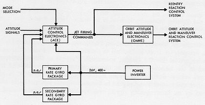
Function block diagram
Encyclopedia
A function block diagram is a block diagram
that describes a function between input variables and output variables. A function is described as a set of elementary blocks. Input and output variables are connected to blocks by connection lines. An output of a block may also be connected to an input of another block:
 Inputs and outputs of the blocks are wired together with connection lines, or links. Single lines may be used to connect two logical points of the diagram:
The connection is oriented, meaning that the line carries associated data from the left end to the right end. The left and right ends of the connection line must be of the same type.
Multiple right connection, also called divergence can be used to broadcast information from its left end to each of its right ends. All ends of the connection must be of the same type.
Function block diagram is one of five languages for logic
or control
configuration
supported by standard
IEC 61131-3
for a control system
such as a Programmable Logic Controller
(PLC) or a Distributed Control System
(DCS). The other supported languages are ladder logic
, sequential function chart
, structured text
, and instruction list
.
Block diagram
Block diagram is a diagram of a system, in which the principal parts or functions are represented by blocks connected by lines, that show the relationships of the blocks....
that describes a function between input variables and output variables. A function is described as a set of elementary blocks. Input and output variables are connected to blocks by connection lines. An output of a block may also be connected to an input of another block:

- An input variable and an input of a block
- An output of a block and an input of another block
- An output of a block and an output variable
The connection is oriented, meaning that the line carries associated data from the left end to the right end. The left and right ends of the connection line must be of the same type.
Multiple right connection, also called divergence can be used to broadcast information from its left end to each of its right ends. All ends of the connection must be of the same type.
Function block diagram is one of five languages for logic
Logic
In philosophy, Logic is the formal systematic study of the principles of valid inference and correct reasoning. Logic is used in most intellectual activities, but is studied primarily in the disciplines of philosophy, mathematics, semantics, and computer science...
or control
Control theory
Control theory is an interdisciplinary branch of engineering and mathematics that deals with the behavior of dynamical systems. The desired output of a system is called the reference...
configuration
Computer configuration
In communications or computer systems, a configuration is an arrangement of functional units according to their nature, number, and chief characteristics. Often, configuration pertains to the choice of hardware, software, firmware, and documentation...
supported by standard
Standardization
Standardization is the process of developing and implementing technical standards.The goals of standardization can be to help with independence of single suppliers , compatibility, interoperability, safety, repeatability, or quality....
IEC 61131-3
IEC 61131-3
IEC 61131-3 is the third part of the open international standard IEC 61131 for programmable logic controllers, and was first published in December 1993 by the IEC...
for a control system
Control system
A control system is a device, or set of devices to manage, command, direct or regulate the behavior of other devices or system.There are two common classes of control systems, with many variations and combinations: logic or sequential controls, and feedback or linear controls...
such as a Programmable Logic Controller
Programmable logic controller
A programmable logic controller or programmable controller is a digital computer used for automation of electromechanical processes, such as control of machinery on factory assembly lines, amusement rides, or light fixtures. PLCs are used in many industries and machines...
(PLC) or a Distributed Control System
Distributed control system
A distributed control system refers to a control system usually of a manufacturing system, process or any kind of dynamic system, in which the controller elements are not central in location but are distributed throughout the system with each component sub-system controlled by one or more...
(DCS). The other supported languages are ladder logic
Ladder logic
Ladder logic is a programming language that represents a program by a graphical diagram based on the circuit diagrams of relay logic hardware. It is primarily used to develop software for programmable logic controllers used in industrial control applications...
, sequential function chart
Sequential function chart
Sequential function chart is a graphical programming language used for PLCs. It is one of the five languages defined by IEC 61131-3 standard...
, structured text
Structured text
Structured text is one of the 5 languages supported by the IEC 61131-3 standard. It is designed for programmable logic controllers . It is a high level language that is block structured and syntactically resembles Pascal. All of the languages share IEC61131 Common Elements...
, and instruction list
Instruction list
Instruction List is one of the 5 languages supported by the IEC 61131-3 standard. It is designed for programmable logic controllers . It is a low level language and resembles assembly. All of the languages share IEC61131 Common Elements...
.
See also
- Function modelFunction modelA function model or functional model in systems engineering and software engineering is a structured representation of the functions within the modeled system or subject area....
- Functional flow block diagramFunctional flow block diagramA Functional Flow Block Diagram is a multi-tier, time-sequenced, step-by-step flow diagram of a system’s functional flow.The FFBD notation was developed in the 1950s, and is widely used in classical systems engineering...

