
Geometric design of roads
Encyclopedia
The geometric design of roadways deals with the positioning of the physical elements of the roadway according to standards and constraints. The basic objective in geometric design is to provide a smooth-flowing, crash-free facility. Geometric roadway design can be broken into three main parts: alignment, profile and cross-section. Combined, they provide a three-dimensional layout for a roadway.
The alignment is the route of the road, defined as a series of horizontal tangents and curves.
The profile is the vertical aspect of the road, including crest and sag curves, and the straight grades connecting them.
The cross section shows the position and number of vehicle and bicycle lanes and sidewalks, along with their cross slope or banking. Cross sections also show drainage features, pavement structure and other items outside the category of geometric design.
, vehicle type, road grade (slope), view obstructions, and stopping distance. With proper application of guidelines, along with good engineering judgement, an engineer can design a roadway that is comfortable, safe, and appealing to the eye. The guidelines take into account speed, vehicle type, road grade (slope), view obstructions, and stopping distance.
The primary US standard is the A Policy on Geometric Design of Highways and Streets published by the American Association of State Highway and Transportation Officials
(AASHTO). Other standards include the Australian Guide to Road Design, and the British Design Manual for Roads.
Vertical curves are used to provide a gradual change from one road slope to another, so that vehicles may smoothly navigate grade changes as they travel.
Sag vertical curves are those that have a tangent slope at the end of the curve that is higher than that of the beginning of the curve. When driving on a road, a sag curve would appear as a valley, with the vehicle first going downhill before reaching the bottom of the curve and continuing uphill or level.
Crest vertical curves are those that have a tangent slope at the end of the curve that is lower than that of the beginning of the curve. When driving on a crest curve, the road appears as a hill, with the vehicle first going uphill before reaching the top of the curve and continuing downhill.
The profile also affects road drainage. Very flat roads and sag curves may have poor drainage, and steep roads will have high velocity flows.
Vertical curves are parabolae
.
BVC = begin of vertical curve
EVT = end of vertical tangent
G1 = initial roadway (tangent)slope
G2 = final roadway (tangent)slope
 = Height of eye above roadway, measured in meters or feet
 = Height of object above roadway, measured in meters or feet
L = curve length (along the x-axis)
PVI = point of vertical interception (intersection of initial and final grades)
tangent elevation = elevation of a point along the initial tangent
x = distance from PTC/BVC
Y (offset) = vertical distance from the initial tangent to the curve
Y’ = curve elevation = tangent elevation - offset
The most important design criterion for these curves is headlight sight distance. When a driver is driving on a sag curve at night, the sight distance is limited by the higher grade in front of the vehicle. This distance must be long enough that the driver can see an obstruction in the road and stop the vehicle within the headlight sight distance. The headlight sight distance (S) is determined by the angle of the headlight and angle of the tangent slope at the end of the curve. By first finding the headlight sight distance (S) and then solving for the curve length (L) in each of the equations below, the correct curve length can be determined. If the SL curve length is smaller than the headlight sight distance, then this number can be used. If it is larger, this value cannot be used.
These equations assume that the headlights are 600 millimetres (2 ft) above the ground, and the headlight beam diverges 1 degree above the longitudinal axis of the vehicle
The most important design criteria for these curves is stopping sight distance. As a vehicle comes over the top of a crest vertical curve, the driver must be able to see any obstructions that lie ahead within a safe stopping distance. If a car on the other side of the hill is stalled or there is an animal in the vehicle's lane, the driver must see the obstruction and be able to stop the car within the stopping sight distance. The stopping sight distance (S) is determined by the speed limit on a road. By first finding the stopping sight distance (S) and then solving for the curve length (L) in each of the equations below, the correct curve length can be determined. If the SL curve length is smaller than the stopping sight distance, then this number can be used. If it is larger, this value cannot be used.
Sight Distance < Curve Length (S
The alignment is the route of the road, defined as a series of horizontal tangents and curves.
The profile is the vertical aspect of the road, including crest and sag curves, and the straight grades connecting them.
The cross section shows the position and number of vehicle and bicycle lanes and sidewalks, along with their cross slope or banking. Cross sections also show drainage features, pavement structure and other items outside the category of geometric design.
Design standards
Roads are designed in conjunction with design guidelines and standards. These are adopted by state and national authorities. Design guidelines take into account speedSpeed
In kinematics, the speed of an object is the magnitude of its velocity ; it is thus a scalar quantity. The average speed of an object in an interval of time is the distance traveled by the object divided by the duration of the interval; the instantaneous speed is the limit of the average speed as...
, vehicle type, road grade (slope), view obstructions, and stopping distance. With proper application of guidelines, along with good engineering judgement, an engineer can design a roadway that is comfortable, safe, and appealing to the eye. The guidelines take into account speed, vehicle type, road grade (slope), view obstructions, and stopping distance.
The primary US standard is the A Policy on Geometric Design of Highways and Streets published by the American Association of State Highway and Transportation Officials
American Association of State Highway and Transportation Officials
AASHTO, the American Association of State Highway and Transportation Officials, is a standards setting body which publishes specifications, test protocols and guidelines which are used in highway design and construction throughout the United States...
(AASHTO). Other standards include the Australian Guide to Road Design, and the British Design Manual for Roads.
Profile
The profile of a road consists of road slopes, called grades, connected by vertical curves.Vertical curves are used to provide a gradual change from one road slope to another, so that vehicles may smoothly navigate grade changes as they travel.
Sag vertical curves are those that have a tangent slope at the end of the curve that is higher than that of the beginning of the curve. When driving on a road, a sag curve would appear as a valley, with the vehicle first going downhill before reaching the bottom of the curve and continuing uphill or level.
Crest vertical curves are those that have a tangent slope at the end of the curve that is lower than that of the beginning of the curve. When driving on a crest curve, the road appears as a hill, with the vehicle first going uphill before reaching the top of the curve and continuing downhill.
The profile also affects road drainage. Very flat roads and sag curves may have poor drainage, and steep roads will have high velocity flows.
Vertical curves are parabolae
Parabola
In mathematics, the parabola is a conic section, the intersection of a right circular conical surface and a plane parallel to a generating straight line of that surface...
.
Terminology
A = absolute value of the difference in grades (initial minus final, expressed in percent)BVC = begin of vertical curve
EVT = end of vertical tangent
G1 = initial roadway (tangent)slope
G2 = final roadway (tangent)slope
= Height of eye above roadway, measured in meters or feet = Height of object above roadway, measured in meters or feetL = curve length (along the x-axis)
PVI = point of vertical interception (intersection of initial and final grades)
tangent elevation = elevation of a point along the initial tangent
x = distance from PTC/BVC
Y (offset) = vertical distance from the initial tangent to the curve
Y’ = curve elevation = tangent elevation - offset
Sag Curves
Sag vertical curves are curves which, when viewed from the side, are concave upwards. This includes vertical curves at valley bottoms, but it also includes locations where an uphill grade becomes steeper, or a downhill grade becomes less steep.The most important design criterion for these curves is headlight sight distance. When a driver is driving on a sag curve at night, the sight distance is limited by the higher grade in front of the vehicle. This distance must be long enough that the driver can see an obstruction in the road and stop the vehicle within the headlight sight distance. The headlight sight distance (S) is determined by the angle of the headlight and angle of the tangent slope at the end of the curve. By first finding the headlight sight distance (S) and then solving for the curve length (L) in each of the equations below, the correct curve length can be determined. If the S
| Units | Sight Distance < Curve Length (S| Sight Distance > Curve Length (S>L) |
|
|---|---|---|
| Metric |  |
 |
| US Customary |  |
 |
These equations assume that the headlights are 600 millimetres (2 ft) above the ground, and the headlight beam diverges 1 degree above the longitudinal axis of the vehicle
Crest Curves
Crest vertical curves are curves which, when viewed from the side, are convex upwards. This includes vertical curves at hill crests, but it also includes locations where an uphill grade becomes less steep, or a downhill grade becomes steeper.The most important design criteria for these curves is stopping sight distance. As a vehicle comes over the top of a crest vertical curve, the driver must be able to see any obstructions that lie ahead within a safe stopping distance. If a car on the other side of the hill is stalled or there is an animal in the vehicle's lane, the driver must see the obstruction and be able to stop the car within the stopping sight distance. The stopping sight distance (S) is determined by the speed limit on a road. By first finding the stopping sight distance (S) and then solving for the curve length (L) in each of the equations below, the correct curve length can be determined. If the S
Sight Distance < Curve Length (S
Alignment
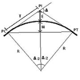
Horizontal alignment in road design consists of straight sections of road, known as tangents, connected by horizontal curves. The design of a horizontal curve entails the determination of a minimum radius (based on speed limit), curve length, and objects obstructing the view of the driver. , Using AASHTO standards, an engineer works to design a road that is safe and comfortable. If a horizontal curve has a high speed and a small radius of curvature, an increased superelevation (bank) is needed in order to assure safety. If there is an object obstructing the view around a corner or curve, the engineer must work to ensure that drivers can see far enough to stop to avoid an accident or accelerate to join traffic.
Terminology

R = Radius
PC = Point of Curvature (point at which the curve begins)
PT = Point of Tangent (point at which the curve ends)
PI = Point of Intersection (point at which the two tangents intersect)
T = Tangent Length
C = Long Chord Length (straight line between PC and PT)
L = Curve Length
M = Middle Ordinate, now known as HSO - Horizontal Sightline Offset (distance from sight-obstructing object to the middle of the outside lane)
e = Rate of Superelevation
 = Coefficient of Side Friction
u = Vehicle Speed
 = Deflection Angle
Geometry


Cross slope
This concept deals with the horizontal or lateral (cross) slope of a roadway. If a road were completely level, water would drain off it very slowly. This would creat problems with hydroplaningHydroplaningHydroplaning and hydroplane may refer to:* Aquaplaning, also known as hydroplaning, a loss of steering or braking control when a layer of water prevents direct contact between tires and the road, runway, or other surface....
, and ice accumulation in cold weather.
In a tangent (straight) section, the road surface is commonly sloped at 1-2% in order to achieve drainage flow of surface water off of the subject roadway. Cross slopes of this magnitude, especially when applied in both directions of travel with a crown point along the centerline of a roadway are commonly referred to as "normal crown" and are generally imperceptible to traveling motorists.
In curved sections, the outside edge of the road is superelevated above the centerline. Since the road is sloped down to the inside of the curve, gravity pulls the vehicle down towards the inside of the curve.This allows gravity to help provide some of the centripital force needed to go around the curve.
Superelevation slopes of up to 4 to 10% are applied in order to aid motorists in safely traversing these sections while maintaining entry speed of the vehicle along the length of the curve. An upper bound of 12% was chosen to reflect the effects of construction and maintenance practices, as well as the difficulty of driving a steep cross slope at low speeds. In areas that get significant snow and ice, most agencies use a maximum cross slope of 6 to 8%. Cross slopes steeper than that make it difficult to traverse the slope when the surface is icy. The lower bound of 4% is mostly used on urban roadways where speeds are lower, and where steeper slopes would raise the outside road edge above adjacent properties.
The equation for the desired radius of a curve is found below taking into account factors for speed and superelevation rates (e) of a given roadway section. This equation can be rearranged algebraically to provide instead for desired rates of superelevation based on the design speed of a roadway and the radius to be used in a curved section.

The American Association of State Highway and Transportation officials (AASHTO) provides a table from which desired superelevation rates can be easily interpolated based on the design speed and radius of a curved section of roadway. This table can also be seen reprinted in many state roadway design guides and manuals in the U.S.
Alignment
Horizontal alignment in road design consists of straight sections of road, known as tangents, connected by horizontal curves. The design of a horizontal curve entails the determination of a minimum radius (based on speed limit), curve length, and objects obstructing the view of the driver. , Using AASHTO standards, an engineer works to design a road that is safe and comfortable. If a horizontal curve has a high speed and a small radius of curvature, an increased superelevation (bank) is needed in order to assure safety. If there is an object obstructing the view around a corner or curve, the engineer must work to ensure that drivers can see far enough to stop to avoid an accident or accelerate to join traffic.Terminology
R = Radius
PC = Point of Curvature (point at which the curve begins)
PT = Point of Tangent (point at which the curve ends)
PI = Point of Intersection (point at which the two tangents intersect)
T = Tangent Length
C = Long Chord Length (straight line between PC and PT)
L = Curve Length
M = Middle Ordinate, now known as HSO - Horizontal Sightline Offset (distance from sight-obstructing object to the middle of the outside lane)
e = Rate of Superelevation
= Coefficient of Side Frictionu = Vehicle Speed
= Deflection Angle Geometry
Cross slope
This concept deals with the horizontal or lateral (cross) slope of a roadway. If a road were completely level, water would drain off it very slowly. This would creat problems with hydroplaningHydroplaning
Hydroplaning and hydroplane may refer to:* Aquaplaning, also known as hydroplaning, a loss of steering or braking control when a layer of water prevents direct contact between tires and the road, runway, or other surface....
, and ice accumulation in cold weather.
In a tangent (straight) section, the road surface is commonly sloped at 1-2% in order to achieve drainage flow of surface water off of the subject roadway. Cross slopes of this magnitude, especially when applied in both directions of travel with a crown point along the centerline of a roadway are commonly referred to as "normal crown" and are generally imperceptible to traveling motorists.
In curved sections, the outside edge of the road is superelevated above the centerline. Since the road is sloped down to the inside of the curve, gravity pulls the vehicle down towards the inside of the curve.This allows gravity to help provide some of the centripital force needed to go around the curve.
Superelevation slopes of up to 4 to 10% are applied in order to aid motorists in safely traversing these sections while maintaining entry speed of the vehicle along the length of the curve. An upper bound of 12% was chosen to reflect the effects of construction and maintenance practices, as well as the difficulty of driving a steep cross slope at low speeds. In areas that get significant snow and ice, most agencies use a maximum cross slope of 6 to 8%. Cross slopes steeper than that make it difficult to traverse the slope when the surface is icy. The lower bound of 4% is mostly used on urban roadways where speeds are lower, and where steeper slopes would raise the outside road edge above adjacent properties.
The equation for the desired radius of a curve is found below taking into account factors for speed and superelevation rates (e) of a given roadway section. This equation can be rearranged algebraically to provide instead for desired rates of superelevation based on the design speed of a roadway and the radius to be used in a curved section.
The American Association of State Highway and Transportation officials (AASHTO) provides a table from which desired superelevation rates can be easily interpolated based on the design speed and radius of a curved section of roadway. This table can also be seen reprinted in many state roadway design guides and manuals in the U.S.