
Tuned radio frequency receiver
Encyclopedia
Amplifier
Generally, an amplifier or simply amp, is a device for increasing the power of a signal.In popular use, the term usually describes an electronic amplifier, in which the input "signal" is usually a voltage or a current. In audio applications, amplifiers drive the loudspeakers used in PA systems to...
s followed by circuits to detect and amplify the audio
Sound
Sound is a mechanical wave that is an oscillation of pressure transmitted through a solid, liquid, or gas, composed of frequencies within the range of hearing and of a level sufficiently strong to be heard, or the sensation stimulated in organs of hearing by such vibrations.-Propagation of...
signal. Prevalent in the early 20th century, it can be difficult to operate because each stage must be individually tuned to the station's frequency
Frequency
Frequency is the number of occurrences of a repeating event per unit time. It is also referred to as temporal frequency.The period is the duration of one cycle in a repeating event, so the period is the reciprocal of the frequency...
. It was replaced by the Superheterodyne receiver
Superheterodyne receiver
In electronics, a superheterodyne receiver uses frequency mixing or heterodyning to convert a received signal to a fixed intermediate frequency, which can be more conveniently processed than the original radio carrier frequency...
invented by Edwin Armstrong
Edwin Armstrong
Edwin Howard Armstrong was an American electrical engineer and inventor. Armstrong was the inventor of modern frequency modulation radio....
.
Background
The TRF receiver was patented in 1916 by Ernst AlexandersonErnst Alexanderson
Ernst Frederick Werner Alexanderson was a Swedish-American electrical engineer, who was a pioneer in radio and television development.-Background:...
. His concept was that each stage would amplify the desired signal while reducing the interfering ones.
The significance of the term "tuned radio frequency" is best understood when compared to the Superheterodyne receiver
Superheterodyne receiver
In electronics, a superheterodyne receiver uses frequency mixing or heterodyning to convert a received signal to a fixed intermediate frequency, which can be more conveniently processed than the original radio carrier frequency...
. A tuned radio frequency receiver actually tunes the receiver on the true radio frequency whereas the Superheterodyne receiver
Superheterodyne receiver
In electronics, a superheterodyne receiver uses frequency mixing or heterodyning to convert a received signal to a fixed intermediate frequency, which can be more conveniently processed than the original radio carrier frequency...
, tunes the desired signal after conversion to an intermediate frequency. Many homemade radios constructed by enthusiasts today, are tuned radio receivers, and these can range from single stage to multi-stage receivers.
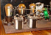
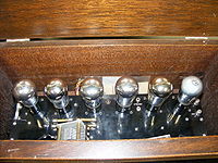
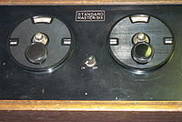
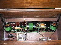
Antique TRF receivers can often be identified by their cabinets. They typically have a long, low appearance, with a flip-up lid for access to the vacuum tube
Vacuum tube
In electronics, a vacuum tube, electron tube , or thermionic valve , reduced to simply "tube" or "valve" in everyday parlance, is a device that relies on the flow of electric current through a vacuum...
s and tuned circuits. On their front panels there are typically two or three large dials, each controlling the tuning for one stage. Inside, along with several vacuum tubes, there will be a series of large coils. These will sometimes be tilted slightly to reduce interaction between their magnetic field
Magnetic field
A magnetic field is a mathematical description of the magnetic influence of electric currents and magnetic materials. The magnetic field at any given point is specified by both a direction and a magnitude ; as such it is a vector field.Technically, a magnetic field is a pseudo vector;...
s.
A problem with the TRF receiver in the time of triode
Triode
A triode is an electronic amplification device having three active electrodes. The term most commonly applies to a vacuum tube with three elements: the filament or cathode, the grid, and the plate or anode. The triode vacuum tube was the first electronic amplification device...
vacuum tubes was that interelectrode capacitance (the so-called Miller capacitance
Miller effect
In electronics, the Miller effect accounts for the increase in the equivalent input capacitance of an inverting voltage amplifier due to amplification of the effect of capacitance between the input and output terminals...
) can cause instability and oscillation
Oscillation
Oscillation is the repetitive variation, typically in time, of some measure about a central value or between two or more different states. Familiar examples include a swinging pendulum and AC power. The term vibration is sometimes used more narrowly to mean a mechanical oscillation but sometimes...
. In 1922, Louis Alan Hazeltine
Louis Alan Hazeltine
Louis Alan Hazeltine was an engineer and physicist, the inventor of the Neutrodyne circuit, and the Hazeltine-Fremodyne Superregenerative circuit. He was the founder of the Hazeltine Corporation....
invented the technique of neutralization which uses an additional winding on the output or input tuned circuit to introduce an opposing signal which can cancel that capacitance, when properly adjusted. This was used in the popular Neutrodyne
Neutrodyne
The Neutrodyne was a particular type of Tuned Radio Frequency radio receiver, in which the instability-causing inter-electrode capacitance of the triode RF tubes is cancelled out or "neutralized"...
series of TRF receivers. The later adoption of the tetrode
Tetrode
A tetrode is an electronic device having four active electrodes. The term most commonly applies to a two-grid vacuum tube. It has the three electrodes of a triode and an additional screen grid which significantly changes its behaviour.-Control grid:...
vacuum tube eliminated the Miller capacitance and the need for this touchy circuitry.
How it works
A 3 stage TRF receiver includes a RF stage, a detector stage and an audio stage: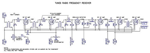
Grid-leak detector
A grid-leak detector is a combination diode rectifier and audio amplifier used as a detector in vacuum tube AM radio receivers.The grid leak is the small current through the grid of a vacuum tube caused by the small negative EMF which is present in all vacuum tubes as a result of a space charge...
.
Disadvantages of TRF receiver
characterizes the TRF's disadvantages as "poor selectivity and low sensitivity in proportion to the number of tubes employed. They are accordingly practically obsolete." Selectivity requires narrow bandwidth, and narrow bandwidth at a high radio frequency implies high Q or many filter sections. For contrast, a superheterodyne receiver can translate the incoming high radio frequency to a lower intermediate frequency where selectivity is easier to achieve.An additional problem for the TRF receiver is tuning different frequencies. All the tuned circuits need to track to keep the narrow bandwidth tuning. Keeping several tuned circuits aligned is difficult. For contrast, a superheterodyne receiver only needs to track the RF and LO stages; the onerous selectivity requirements are confined to the IF amplifier which is fixed-tuned.
Although a TRF receiver can not be engineered for a high degree of selectivity relative to its carrier frequency, there is no reason it cannot reach the same level of sensitivity as other designs. The 1930's era BC-AN-229/429 military receiver was a six-valve design covering 201 to 398 KHz and 2.5 to 7.7 MHz (requiring several sets of plug-in coils to cover those ranges). This equipment probably exemplifies the limit of T.R.F. performance. Although the receiver bandwidth does vary, as noted above, the sensitivity of the set was around 8 microvolts for 10 milliwatts of audio output, comparable to that of the famous AN/ARC-5 superhet receiver that superseded it.
Modern Usage
Although the TRF design heralds from the early years of radio and has been largely superseded by superheterodyne and other circuits, it was 'resurrected' in 1972 in silicon as the ZN414ZN414
The ZN414 was a low cost, single-chip AM radio integrated circuit. Launched in 1972, the part was designed and supplied by Ferranti, but was also available from GEC-Plessey...
TRF radio integrated circuit
Integrated circuit
An integrated circuit or monolithic integrated circuit is an electronic circuit manufactured by the patterned diffusion of trace elements into the surface of a thin substrate of semiconductor material...
from Ferranti
Ferranti
Ferranti or Ferranti International plc was a UK electrical engineering and equipment firm that operated for over a century from 1885 until it went bankrupt in 1993. Known primarily for defence electronics, the Company was once a constituent of the FTSE 100 Index but ceased trading in 1993.The...
, thus affording the design a new lease of life in hobbyist radio projects, kits and some commercial products.
See also
- Tuner (electronics)
- Crystal radio
- Regenerative circuitRegenerative circuitThe regenerative circuit or "autodyne" allows an electronic signal to be amplified many times by the same vacuum tube or other active component such as a field effect transistor. It consists of an amplifying vacuum tube or transistor with its output connected to its input through a feedback...
- Superheterodyne receiverSuperheterodyne receiverIn electronics, a superheterodyne receiver uses frequency mixing or heterodyning to convert a received signal to a fixed intermediate frequency, which can be more conveniently processed than the original radio carrier frequency...
- Low IF receiverLow IF receiverIn a low-IF receiver, the RF signal is mixed down to a non-zero low or moderate intermediate frequency, typically a few megahertz. Low-IF receiver topologies have many of the desirable properties of zero-IF architectures, but avoid the DC offset and 1/f noise problems.The use of a non-zero IF...

