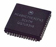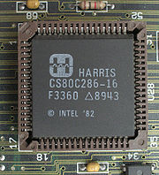
Plastic leaded chip carrier
Encyclopedia


Chip carrier
A chip carrier, also known as a chip container or chip package, is a container for a transistor or an integrated circuit. The carrier usually provides metal leads, or "pins", which are sturdy enough to electrically and mechanically connect the fragile chip to a circuit board. This connection may be...
with a equiangular
Equiangular polygon
In Euclidean geometry, an equiangular polygon is a polygon whose vertex angles are equal. If the lengths of the sides are also equal then it is a regular polygon.The only equiangular triangle is the equilateral triangle...
plastic housing. It is a reduced cost evolution of the ceramic leadless chip carrier (CLCC).
A premolded PLCC was originally released in 1976, but did not see much market adoption. Texas Instruments later released a postmolded variant that was soon adopted by most major semiconductor companies. The JEDEC
JEDEC
The JEDEC Solid State Technology Association, formerly known as the Joint Electron Devices Engineering Council , is an independent semiconductor engineering trade organization and standardization body...
trade group started a task force in 1981 to categorize PLCCs, with the MO-047 standard released in 1984 for square packages and the MO-052 standard released in 1985 for rectangular packages.
The PLCC utilizes a "J"-lead
Lead (electronics)
In electronics, a lead is an electrical connection consisting of a length of wire or soldering pad that comes from a device. Leads are used for physical support, to transfer power, to probe circuits , and to transmit information...
with pin spacings of 0.05" (1.27 mm). Lead counts range from 20 to 84. PLCC packages can be square or rectangular. Body widths range from 0.35" to 1.15". The PLCC “J” Lead configuration requires less board space versus equivalent gull leaded components. The PLCC is preferred over DIP
Dual in-line package
In microelectronics, a dual in-line package is an electronic device package with a rectangular housing and two parallel rows of electrical connecting pins. The package may be through-hole mounted to a printed circuit board or inserted in a socket.A DIP is usually referred to as a DIPn, where n is...
style chip carriers when lead counts exceed 40 pins due to the PLCC's more efficient use of board surface area.
The heatspreader versions are identical in form factor to the standard non-heatspreader versions. Both versions are JEDEC compliant in all respects. The heatspreader versions give the system designer greater latitude in thermally enhanced board level and / or system design. RoHs compliant, lead-free & green material sets are now qualified standards.
A PLCC circuit may either be installed in a PLCC socket or surface-mounted
Surface-mount technology
Surface mount technology is a method for constructing electronic circuits in which the components are mounted directly onto the surface of printed circuit boards . An electronic device so made is called a surface mount device...
. PLCC sockets may in turn be surface mounted, or use through-hole technology
Through-hole technology
Through-hole technology, also spelled "thru-hole", refers to the mounting scheme used for electronic components that involves the use of leads on the components that are inserted into holes drilled in printed circuit boards and soldered to pads on the opposite side either by manual assembly by...
. The motivation for a surface-mount PLCC socket would be when working with devices that cannot withstand the heat involved during the reflow process, or to allow for component replacement without reworking. Using a PLCC socket may be necessary in situations where the device requires stand-alone programming, such as some flash memory
Flash memory
Flash memory is a non-volatile computer storage chip that can be electrically erased and reprogrammed. It was developed from EEPROM and must be erased in fairly large blocks before these can be rewritten with new data...
devices. Some through-hole sockets are designed for prototyping with wire wrap
Wire wrap
Wire wrap is a technology used to assemble electronics. It is a method to construct circuit boards without having to make a printed circuit board. Wires can be wrapped by hand or by machine, and can be hand-modified afterwards. It was popular for large-scale manufacturing in the 60s and early 70s,...
ping.
A specialized tool called a PLCC extractor facilitates the removal of a PLCC from a socket.
This package is still used for a wide variety of device types, which would include memory, processors, controllers, ASIC, DSP, etc. Applications range from consumer products through automotive and aerospace.
See also
- Integrated circuit packagingIntegrated circuit packagingIntegrated circuit packaging is the final stage of semiconductor device fabrication per se, followed by IC testing.Packaging in ceramic or plastic prevents physical damage and corrosion and supports the electrical contacts required to assemble the integrated circuit into a system.In the integrated...
- Leadless chip carrierLeadless chip carrierA leadless chip carrier is a type of packaging for integrated circuits that has no "leads", but instead has rounded pins through the edges of the ceramic or molded plastic package....
- Chip carrierChip carrierA chip carrier, also known as a chip container or chip package, is a container for a transistor or an integrated circuit. The carrier usually provides metal leads, or "pins", which are sturdy enough to electrically and mechanically connect the fragile chip to a circuit board. This connection may be...
Chip packaging and package types list

