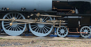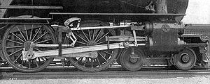
Walschaert valve gear
Encyclopedia

Steam engine
A steam engine is a heat engine that performs mechanical work using steam as its working fluid.Steam engines are external combustion engines, where the working fluid is separate from the combustion products. Non-combustion heat sources such as solar power, nuclear power or geothermal energy may be...
valve gear
Valve gear
The valve gear of a steam engine is the mechanism that operates the inlet and exhaust valves to admit steam into the cylinder and allow exhaust steam to escape, respectively, at the correct points in the cycle...
invented by Belgian
Belgium
Belgium , officially the Kingdom of Belgium, is a federal state in Western Europe. It is a founding member of the European Union and hosts the EU's headquarters, and those of several other major international organisations such as NATO.Belgium is also a member of, or affiliated to, many...
railway mechanical engineer
Mechanical engineering
Mechanical engineering is a discipline of engineering that applies the principles of physics and materials science for analysis, design, manufacturing, and maintenance of mechanical systems. It is the branch of engineering that involves the production and usage of heat and mechanical power for the...
Egide Walschaerts
Egide Walschaerts
Egide Walschaerts was a Belgian mechanical engineer, best known as the inventor of the Walschaerts valve gear for use in steam locomotives.He was born in Belgium at Fl. Mechelen...
in 1844. The gear is sometimes named without the final "s", since it was incorrectly patent
Patent
A patent is a form of intellectual property. It consists of a set of exclusive rights granted by a sovereign state to an inventor or their assignee for a limited period of time in exchange for the public disclosure of an invention....
ed under that name. It was extensively used in steam locomotive
Steam locomotive
A steam locomotive is a railway locomotive that produces its power through a steam engine. These locomotives are fueled by burning some combustible material, usually coal, wood or oil, to produce steam in a boiler, which drives the steam engine...
s from the late 19th century until the end of the steam era.
History

Stephenson valve gear
The Stephenson valve gear or Stephenson link or shifting link is a simple design of valve gear that was widely used throughout the world for all kinds of steam engine. It is named after Robert Stephenson but was actually invented by his employees....
remained the most popularly used valve gear on 19th-century locomotives. The Walschaerts gear had the advantage that it could be mounted entirely on the outside of the locomotives, leaving the space between the frames
Locomotive frame
A locomotive frame is the structure that forms the backbone of the railway locomotive, giving it strength and supporting the superstructure elements such as a cab, boiler or bodywork. The vast majority of locomotives have had a frame structure of some kind...
clear; this caused adoption first among some articulated locomotive
Articulated locomotive
Articulated locomotive usually means a steam locomotive with one or more engine units which can move independent of the main frame. This is done to allow a longer locomotive to negotiate tighter curves...
s. The Mason Bogie
Mason Bogie
The Mason Bogie is a type of articulated steam locomotive suited for sharp curves and uneven track, once commonly used on narrow gauge lines in the United States...
locomotive type was the first to use the Walschaerts gear in North America
North America
North America is a continent wholly within the Northern Hemisphere and almost wholly within the Western Hemisphere. It is also considered a northern subcontinent of the Americas...
.
The first application in Britain was on a Single Fairlie
Fairlie
A Fairlie is a type of articulated steam locomotive that has the driving wheels on bogies. The locomotive may be double-ended or single ended...
0-4-4T, exhibited in Paris in 1878 and purchased by the Swindon, Marlborough and Andover Railway
Swindon, Marlborough and Andover Railway
The Swindon, Marlborough and Andover Railway was one of the constituents of the Midland and South Western Junction Railway. It received Parliamentary approval on 21 July 1873 and construction began in 1875 ....
in 1883. According to Ahrons, the locomotive saw very little service as nobody seems to have known how to set the valves and this led to enormous coal consumption.
In the 20th century, the Walschaerts valve gear was the most commonly used type, especially on larger locomotives. In Europe
Europe
Europe is, by convention, one of the world's seven continents. Comprising the westernmost peninsula of Eurasia, Europe is generally 'divided' from Asia to its east by the watershed divides of the Ural and Caucasus Mountains, the Ural River, the Caspian and Black Seas, and the waterways connecting...
, its use was almost universal, whilst in North America, the Walschaerts gear outnumbered its closest competitor, the Baker valve gear
Baker valve gear
Baker valve gear was the main competitor to Walschaerts valve gear for steam locomotives in the United States. Strictly speaking it was not a valve gear but a variable expansion mechanism adapted to the Walschaerts layout replacing the expansion link and sliding die block...
, by a wide margin.
In Germany
Germany
Germany , officially the Federal Republic of Germany , is a federal parliamentary republic in Europe. The country consists of 16 states while the capital and largest city is Berlin. Germany covers an area of 357,021 km2 and has a largely temperate seasonal climate...
, the Walschaerts gear is often named the Heusinger valve gear after Edmund Heusinger von Waldegg, who invented the mechanism independently in 1849. Heusinger's gear was closer to the form generally adopted, but most authorities accept Walschaerts' invention as sufficiently close to the final form.
Components

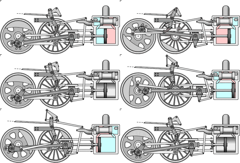
- Fly Crank (shown) or EccentricEccentric (mechanism)In mechanical engineering, an eccentric is a circular disk solidly fixed to a rotating axle with its centre offset from that of the axle ....
(Return Crank) - Fly-Crank/Eccentric/Return-Crank Rod
- Reach Rod
- Lifting Link
- Lifting Arm
- Reverse Arm & Shaft (Weighshaft)
- Expansion Link, with Die Block movable along dashed lines
- Radius Bar/Rod, pivoted to Die Block
- Crosshead Arm (Drop Link)
- Valve Stem Guide
- Union Link (Anchor Link)
- Combination Lever
- Valve Stem
- Valve Spindle
Purpose
The Walschaerts valve gear is an improvement on the earlier Stephenson valve gear in that it enables the engineer to operate the steam engine in a continuous range of settings from maximum economy to maximum power. At any setting, the valve gear satisfies the following two conditions:- At the instant when the space on one side of the piston starts to expand, i.e. at the very start of a stroke, the valve opens to admit steam from the boiler into that space. The pressure of this steam provides the driving force.
- At the instant when the space on one side of the piston starts to contract, the valve starts to release steam from that space to the atmosphere, so as not to impede the movement of the piston.
These functions are shown in the animated diagram below.
In an economical setting, steam is admitted to the expanding space for only part of the stroke; at a point set by the engineer, the intake is cut off. Since the exhaust is also shut, during the rest of the stroke the steam that has entered the cylinder expands in isolation, and so its pressure decreases. For maximum economy, the engineer carefully sets the cutoff point so that, when the exhaust valve opens, the steam is down to exactly atmospheric pressure. Thus, all the mechanical energy available from the steam (in the absence of a condenser) is used.
The Walschaerts valve gear enables the engineer to change the cutoff point without changing the points at which intake starts and at which exhaust starts. With the Stephenson valve gear, in contrast, if the engineer shortens the intake period, the openings of the intake and exhaust are delayed, occurring after a stroke has begun.
Economy also requires that the throttle is wide open, so that no energy is wasted pushing steam through a constriction, and that the boiler pressure is at the maximum safe level to maximize thermal efficiency
Thermal efficiency
In thermodynamics, the thermal efficiency is a dimensionless performance measure of a device that uses thermal energy, such as an internal combustion engine, a boiler, a furnace, or a refrigerator for example.-Overview:...
. For economy, a steam engine is used of a size such that the most economical settings yield the right amount of power most of the time, such as when a train is running at steady speed on level track.
When greater power is necessary, e.g. when gaining speed when pulling out of a station and when ascending a gradient, the Walschaerts valve gear enables the engineer to set the cutoff point near the end of the stroke, so that the full pressure of the boiler is exerted on the piston for almost the entire stroke. With such a setting, when the exhaust opens, the steam in the cylinder is near full boiler pressure. The pressure in the steam at that moment serves no useful purpose; it is wasted driving a sudden pulse of pressure into the atmosphere, but this waste is more than compensated by maximized economy at other times.
This sudden pulse of pressure causes the loud “choo” sound that members of the public associate with steam engines, because they mostly encounter engines at stations, where efficiency is sacrificed as trains pull away. A steam engine well adjusted for efficiency makes a soft “hhHHhh” sound that lasts throughout the exhaust stroke, with the sounds from the two cylinders overlapping to produce a nearly constant sound.
Technical details
The heart of the Walschaerts valve gear is the combination lever. Its lower end moves in phase with the piston rod; its upper end moves 90° out of phase with the piston rod. The valve stem thus moves in a combination of these two motions. Through the reach rod and the radius rod lifter, the engineer adjusts the position of the die block in the expansion link, and thus adjusts the amplitude of the motion of the upper end of the combination lever (including the possibility of reversal of that motion, which reverses the engine).To make possible a period of cutoff for efficiency, the valve is designed so that both intake and exhaust are blocked when the valve rod is in a range centered at the center of its travel. This range is its lap.
When maximum power is sought, the exhaust opens almost immediately after the intake closes. Therefore, the valve must move rapidly through this middle range of cutoff during such operation. Since this rapid transition occurs when the piston passes through dead centre
Dead centre
In a reciprocating engine, the dead centre is the position of a piston in which it is farthest from, or nearest to, the crankshaft. The former is known as top dead centre while the latter is known as bottom dead centre ....
, the motion of the valve must be 90° out of phase with that of the piston rod. The engineer can satisfy these two conditions by moving the reach rod to an extreme position, so that the die block is near an end of the expansion link, where the motion is fastest and its amplitude is greatest. The upper end of the combination lever then dominates the motion of the valve stem; the valve is in the cutoff range only briefly, and its phase is near 90°.
For more efficient operation, the engineer moves the die block near the center of the expansion link. The amplitude of the valve stem’s motion is then lower, and its phase is shifted away from 90°. The Walschaerts valve gear, when correctly designed, provides constant valve lead irrespective of the chosen cutoff
Cutoff (steam engine)
In a steam engine, cutoff is the point in the piston stroke at which the inlet valve is closed. On a steam locomotive, the cutoff is controlled by the reverser....
in both forward and reverse gear. With the piston in the front or rear dead centre
Dead centre
In a reciprocating engine, the dead centre is the position of a piston in which it is farthest from, or nearest to, the crankshaft. The former is known as top dead centre while the latter is known as bottom dead centre ....
positions, the expansion link should be vertical and moving the die block up and down should not alter the valve spindle position.
The amount of lead provided is determined by the proportions of the combination lever and the lap designed into the valve. It can only be changed by changing the proportions of these components.


If this were the only motion made by the valve then the engine would only start if the piston were close to dead centre, and even then the direction in which the engine moved would depend upon whether it was fractionally before or after the dead centre point.
Outside admission valves
Consider the case of outside admission valves such as slide valves.A second motion is superimposed on the crosshead motion to the valve; the return crank provides a motion which leads the crankpin motion by 90 degrees. By choice of position of the reach rod the die block may be moved from top to bottom which superimposes a varying portion of this motion ranging from either 90 degrees in lead ahead of the crank (full forward gear) through none in midgear to 90 degrees lagging the crank (full reverse gear). Lag and lead of these motions are always described relative to the engine moving forwards. The larger the magnitude of the superimposed component, the later the cutoff and thus the less expansion allowed for the steam in the cylinder.
Inside admission valves
For inside admission valves (most piston valves, but there are some exceptions on rebuilt locomotives) the lag and lead motions must be reversed usually by locating the eccentric crank pin 90 degrees after (following) the main crank pin (in forward motion) and the combination rod pivots on the radius rod above the linkage to the valve rods instead of below. This is the case shown in the diagrams above.Layout

Next, the fact that in midgear the valve opening should be the same for the piston in both front and rear dead centre positions is used to find the mid gear position of the pivot between the combination rod and reach rod. In practice the valve spindle length is adjusted to ensure this as part of setting the timing. Also the dimensions of the lead and lap lever are set so that the valve moves twice the lead + lap of the valve.
With the reverser in mid gear position since there should be no superimposed return crank motion, the expansion link die slot should be an arc of a circle centred on the pivot in mid gear and of radius equal to the length of the radius rod. This condition precludes adjustment of the valve gear by altering the length of the radius rod.
The throw of the return crank must now be determined; The actual throw required from the crank is determined from the dimensions of the expansion link.
Variants
There have been many variants of Walschaerts valve gear, including:- Baker valve gearBaker valve gearBaker valve gear was the main competitor to Walschaerts valve gear for steam locomotives in the United States. Strictly speaking it was not a valve gear but a variable expansion mechanism adapted to the Walschaerts layout replacing the expansion link and sliding die block...
- Baguley valve gearBaguley valve gearThe Baguley valve gear is a type of steam engine valve gear invented by Mr E. E. Baguley the draftsman of the W.G. Bagnall company of locomotive manufacturers. It was patented in 1893....
- Bagnall-Price valve gearBagnall-Price valve gearBagnall-Price valve gear is a type of steam engine valve gear developed at locomotive manufacturer W.G. Bagnall as an alternative to the more common Walschaerts valve gear. The gear was patented in 1903 by W.G. Bagnall and T. S. Price, the manager of the works....
- J. T. Marshall valve gearJames Thompson MarshallJames Thompson Marshall was a British railway and mechanical engineer known for inventing the 'Marshall valve gear' for steam locomotive use.-Career and 'Marshall valve gear':...
External links
- Valve Gear Demos Charles Dockstader's Valve Gear Demos
- Program for semi automatical layout of valve gears (Online program for Firefox browser)
- Video: simple explanation of Walschaerts valve gear (with BR Standard Class 5 73096BR standard class 5 73096British Railways Standard Class 5 No. 73096 is a preserved British steam locomotive. Unnamed in service, it is now operated by the Mid-Hants Railway on the Watercress Line between Alresford and Alton....
as the visual aid)

