4-12-2
Encyclopedia

Whyte notation
The Whyte notation for classifying steam locomotives by wheel arrangement was devised by Frederick Methvan Whyte and came into use in the early twentieth century encouraged by an editorial in American Engineer and Railroad Journal...
for the classification of steam locomotive
Steam locomotive
A steam locomotive is a railway locomotive that produces its power through a steam engine. These locomotives are fueled by burning some combustible material, usually coal, wood or oil, to produce steam in a boiler, which drives the steam engine...
s, 4-12-2 represents the wheel arrangement
Wheel arrangement
In rail transport, a wheel arrangement is a system of classifying the way in which wheels are distributed beneath a locomotive.. Several notations exist to describe the wheel assemblies of a locomotive by type, position, and connections, with the adopted notations varying by country...
of four leading wheel
Leading wheel
The leading wheel or leading axle of a steam locomotive is an unpowered wheel or axle located in front of the driving wheels. The axle or axles of the leading wheels are normally located in a truck...
s, twelve coupled driving wheel
Driving wheel
On a steam locomotive, a driving wheel is a powered wheel which is driven by the locomotive's pistons...
s, and two trailing wheel
Trailing wheel
On a steam locomotive, a trailing wheel or trailing axle is generally an unpowered wheel or axle located behind the driving wheels. The axle of the trailing wheels was usually located on a trailing truck...
s.
Other equivalent classifications are:
AAR wheel arrangement
AAR wheel arrangement
The AAR wheel arrangement system is a method of classifying locomotive wheel arrangements that was developed by the Association of American Railroads. It is essentially a simplification of the European UIC classification, and it is widely used in North America to describe diesel and electric...
: 2-F-1
UIC classification
UIC classification
The UIC classification of locomotive axle arrangements describes the wheel arrangement of locomotives, multiple units and trams. It is set out in the International Union of Railways "Leaflet 650 - Standard designation of axle arrangement on locomotives and multiple-unit sets". It is used in much...
: 2′F1′ (also known as German classification and Italian classification)
French classification: 261
Turkish classification
Turkish classification
In the Turkish classification system for railway locomotives, the number of powered axles are followed by the total number of axles. It is identical to the Swiss system except that the latter places a slash between the two numbers.Thus0-6-0 becomes 33...
: 69
Swiss classification: 6/9
This arrangement was named the Union Pacific type, after the only railroad to use it.
Only one type of 4-12-2 was built, the Union Pacific Railroad
Union Pacific Railroad
The Union Pacific Railroad , headquartered in Omaha, Nebraska, is the largest railroad network in the United States. James R. Young is president, CEO and Chairman....
's 9000-series locomotives, 88 of which were built by ALCO
American Locomotive Company
The American Locomotive Company, often shortened to ALCO or Alco , was a builder of railroad locomotives in the United States.-Early history:...
between 1926 and 1930. These locomotives were used to increase the speed of freight trains in flat country, and were fairly successful, but were maintenance nightmares, largely because of their use of an inaccessible third cylinder driving a cranked second driving axle between the frames. There was no inaccessible valve gear to worry about, however. ALCO had obtained permission to use the conjugated valve gear
Gresley conjugated valve gear
The Gresley conjugated valve gear is a valve gear for steam locomotives designed by Sir Nigel Gresley, chief mechanical engineer of the LNER, assisted by Harold Holcroft...
invented by Sir Nigel Gresley
Nigel Gresley
Sir Herbert Nigel Gresley was one of Britain's most famous steam locomotive engineers, who rose to become Chief Mechanical Engineer of the London and North Eastern Railway . He was the designer of some of the most famous steam locomotives in Britain, including the LNER Class A1 and LNER Class A4...
. This system used two hinged levers connected to the outer cylinder's valves to operate the inner cylinder's valve. The 9000 class locomotives were the largest ever to use Gresley gear.
Between 1934 and 1940 eight of the first fifteen locos had their Gresley gear removed and were converted to a "double Walschaerts" valve gear which utilized a double eccentric (return) crank and second link on the right side (similar to the gear Baldwin used on its 3-cylinder experimental compound 4-10-2 #60000
Baldwin 60000
Baldwin 60000 is an experimental steam locomotive built by the Baldwin Locomotive Works in Eddystone, Pennsylvania in 1926, during the height of the railroading industry. It received its number for being the 60,000th locomotive built by Baldwin....
), which operated the valve for the inside cylinder. Union Pacific referred to this system as the "third link." The 4-12-2's constructed from 1928 utilized roller bearings in the Gresley lever bearings, thus none of these engines were converted. The pre-1928 engines not converted received the roller bearing levers in 1940, and no further conversions were made.
During the design phase the third and fourth driving axles were planned to be "blind" (flangeless) in order to improve curve handling, but the use of ALCO's lateral motion device
Lateral motion device
Lateral motion devices permit the axles in some railroad locomotives to move sideways relative to the frame.-Purpose:The coupled driving wheels on steam locomotives were held in a straight line by the locomotive's frame...
s on the first and sixth axles (which allowed the axles to slide up to two inches to the side) made this unnecessary. They had the longest rigid wheelbase in North America, and until 1934
4-14-4
A 4-14-4, in the Whyte notation for the classification of steam locomotives by wheel arrangement, is a locomotive with four leading wheels, fourteen coupled driving wheels in a rigid frame, and four trailing wheels....
, the longest in the world. The trailing truck carried the same axle load as the drivers, which was unusual.
There has been some debate as to whether the first driving axle of the 4-12-2 was cranked to provide clearance for the main rod connected to the second axle. Union Pacific drawings confirm that there was no such crank on the first axle. Instead, the spacing between the first and second axles was increased by 18 in (45.7 cm) to provide the necessary clearance. Based on the published dimensions, this means at its closest the centerline of the inside rod was 11.645 inches from the centerline of the first axle. (UP drawings reproduced in Kratville and Bush's "Union Pacific Type" books show the inside rod 113 inches long and the first and second driver axles 88 inches apart. The inside cylinder axis was inclined 9.5 degrees and was 32 inches above the plane of the driving axles at a point 181 inches ahead of the second driving axle, so the cylinder axis missed the centerline of the second axle by 1-11/16 inches. The rod centerline is closest to the axle when the crank is 54.49 degrees below horizontal.)
| Year | Quantity | Class | Builder | Union Pacific Number | Notes |
|---|---|---|---|---|---|
| 1926 | 1 | UP-1 | Alco 66544 | Union Pacific 9000 | Preserved |
| 1926 | 14 | UP-2 | Alco | Union Pacific 9001–9014 | 9004 to OWR&N 9708, then back to UP 9004 |
| 1928 | 15 | UP-3 | Alco | Union Pacific 9015–9029 | |
| 1928 | 8 | UP-3 | Alco | Oregon-Washington Railroad and Navigation Company 9700–9707 | to Union Pacific 9055–9062 |
| 1929 | 25 | UP-4 | Alco | Union Pacific 9030–9054 | |
| 1930 | 15 | UP-5 | Alco | Union Pacific 9063–9077 | to Oregon Short Line Oregon Short Line Railroad The Oregon Short Line Railroad was a railroad in the U.S. states of Wyoming, Idaho, Utah, Montana and Oregon. The line was as organized the Oregon Short Line Railway in 1881 as a subsidiary of Union Pacific Railway. Union Pacific intended the line to be the shortest route from Wyoming to Oregon... 9500–9514 |
| 1930 | 10 | UP-5 | Alco | Union Pacific 9078–9087 | |
| Total | 88 | ||||
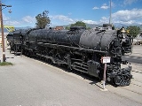
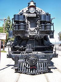
One example survives: Union Pacific 9000 (seen at right) at the Railway and Locomotive Historical Society's museum at the Los Angeles County Fairplex
Fairplex
Fairplex, formerly known as the Los Angeles County Fairgrounds, has been since 1922 the home of the L.A. County Fair. It is located in the city of Pomona, California. The L.A...
in Pomona, California
Pomona, California
-2010:The 2010 United States Census reported that Pomona had a population of 149,058, a slight decline from the 2000 census population. The population density was 6,491.2 people per square mile...
.

